Floating Pins
It is natural to assume that a pin that is not connected to anything is at 0V. In reality, a disconnected pin (also referred to as a floating pin) has an undefined state, as in it may actually have a voltage sufficient to indicate a HIGH signal or it may even randomly switch between having and not having any voltage. This is due to the electrical noise it can pick up from the electrical system in your house or other electric field sources.
This problem is notable when using a switch. If the switch is in the off position, the pin providing the voltage from the switch is expected to be at 0V and therefore provide a LOW signal, indicating that the switch is in the off position. With the possibility of a floating pin having a random voltage, it may continue to send a HIGH signal indicating that the switch is on when it is intended to be off.
Pull-up Resistors
While this concept is explained for your understanding, it is advisable not to actually use physical pull-up or pull-down resistors in your circuit. If the resistor values or connections are incorrect it could damage your microcontroller board or components.
Most microcontroller boards have what is known as an internal pull-up resistor that can be activated for a pin if required using code. Note that there is no INPUT_PULLLDOWN option since that is not recommended.
pinMode(3, INPUT_PULLUP)
To resolve this problem of the unknown state of a floating pin, you can use what is referred to as a pull-up resistor. In this approach, as shown in the illustration below, the input pin (pin 3) is connected to the VCC of the power supply through a resistor. This results in a proper voltage and current (and a HIGH signal) on the pin when the switch is off. When the switch is turned on, it connects the input pin directly to ground. The current now flows through the resistor to ground, and the input pin is grounded and has a clear 0V (and a LOW signal).
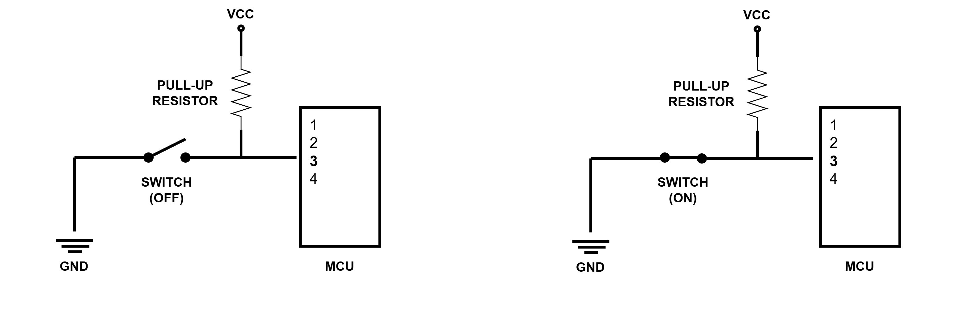
In this approach the resistor is very important as without it the button would connect VCC to ground, which is referred to as a short circuit and is very dangerous.
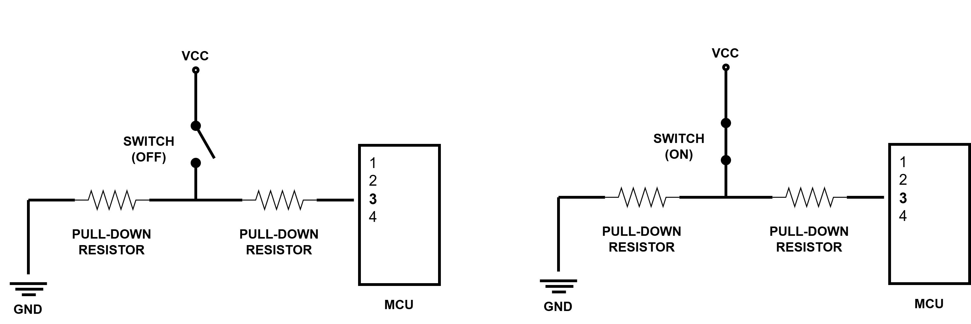
The reverse of a pull-up resistor would be a pull-down resistor. In this approach, as shown in the illustration below, the input pin is connected to the ground of the power supply through a resistor. When the switch is off, it connects the input pin directly to ground and has a clear 0V (and a LOW signal). When the switch is turned on a proper voltage and current (and a HIGH signal) is available on the pin.
Although the pull-up resistor approach is counter-intuitive, since you would normally expect a LOW signal when the button is off, it is more commonly used than the pull-down resistor. The microcontroller program should be coded accordingly.