Pinout Diagrams
A board makes available its microprocessor pins and may add some pins of its own for additional functionality. A pinout diagram indicates the purpose/function of each pin on the board. The pins on a board are labelled, generally using letters and numbers (such as D1, D2, and so on for digital pins, A1, A2, and so on for analog pins, and with specific labels for other functions).
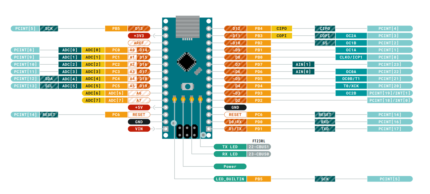
A pinout diagram provides a graphical view of the pins as laid out on a board. An example of a pinout diagram for an Arduino Nano is shown below.
General Guidance for using pins
The microprocessor also has pin numbers with specific functions which are used when the microprocessor is used without a board. When programming boards you have to use the board pin numbers, not the microprocessor pin numbers.
Some pins output a high or a low signal when the board boots up. Any active components connected to these boards will be affected. For example, an LED connected to a pin that outputs a high signal when booting up will light up.