Power Supply
All circuits need a power supply to function. Electronic components (and therefore circuits built with them) work on Direct Current (DC) and generally have a voltage requirement of between 3 and 12 volts with a maximum current of about 2 Amperes.
The various power supply options explained below are generally common across boards. However, since board designs are always changing, you must refer to the latest specifications of the board. You must check the voltage and current rating of each component that you use in the circuit. If you use a power supply that is lower than the component rating, then it may not function correctly. And if you use a higher supply than component rating, then it may get damaged.
DC power supplies can use AC electricity which is supplied to households as an energy source. Such power supplies will employ a transformer to convert the input voltage to a higher or lower AC voltage. A rectifier is used to convert the transformer output voltage to a varying DC voltage, which is passed through an electronic filter to convert it to an unregulated DC voltage. The filter removes most but not every AC voltage variation. The remaining AC voltage is known as ripple.
A switched-mode power supply (SMPS) is an electronic power supply that incorporates a switching regulator to convert electrical power efficiently. Like other power supplies, an SMPS transfers power from an AC source (often mains power) to DC loads, such as a personal computer, while converting voltage and current characteristics. These are expensive and not required for simple circuits but are useful unless you have expensive or sensitive circuits.
DC power supply can also be provided by batteries, but they discharge quickly for frequent replacement or recharging.
There are multiple ways to supply power to a microcontroller board:
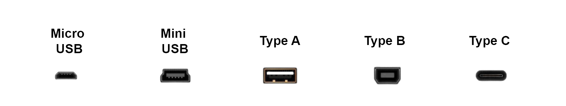
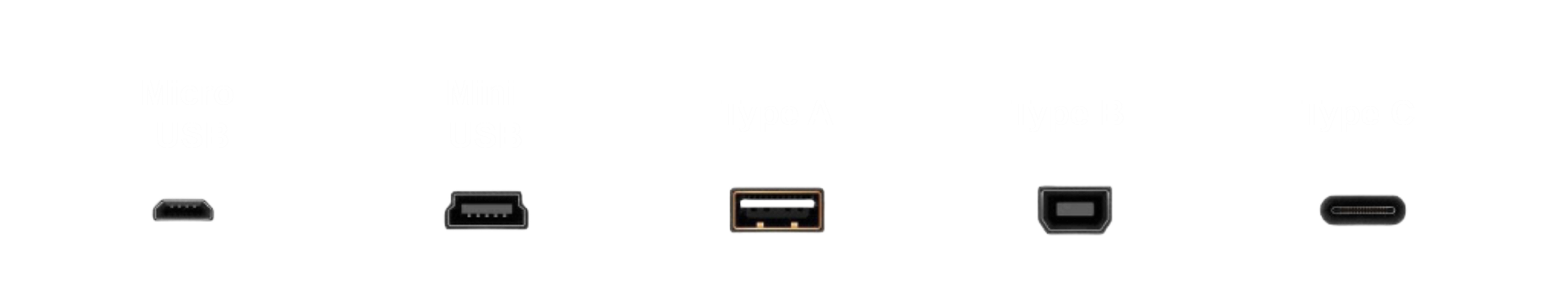
- USB Connector
The board can be powered by connecting it to a computer using an appropriate USB cable depending on the USB connector provided with the board. This provides a regulated supply (typically 5V), and the onboard voltage regulator is not required (it is bypassed). With this power supply the board pins can generally provide a higher current to power more components.
If the circuit needs to run independent of a computer (which is quite often the case once you have finished building and programming it) the USB connector can also be supplied power by a power bank which supplies a regulated voltage of the desired level (typically 5V).
When connected to a computer the USB cable is also used to upload programs to the board from the IDE running on the computer. The cable also acts as a data transmission channel to send data to or receive data from the microcontroller on the computer.
- VIN Pin
If you would like to use a battery without a USB connector you can supply power using wires connected to the VIN and Ground pins on the board. The input supply can range between 6V and 24V. The onboard regulator brings down the voltage to 5V as required by the board.
The VIN pin is connected directly to the input pin of the onboard voltage regulator on boards and therefore it does not have reverse polarity protection, which is required to protect the regulator. Hence, this approach must be used with caution. This approach also limits the current supplied to the boards pins and current-hungry components may not work as well.
- Barrel Jack Connector
Some boards have a barrel jack connector which is a connector that is typically found on an AC to DC converter. The board can then be supplied power from an electrical wall socket. This supply also goes through the onboard voltage regulator (effectively connected to the VIN pins internally) and is subject to similar constraints as using the VIN pins.
The preferred option for beginners is to supply power to a board through the USB connector from the computer or a power bank.